
Submit Chapter news to Beacon Co-Editors and OES Chapter Coordinator
Providence Chapter
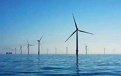
Technical Talk “General Overview of Offshore Wind”
Reported by David Leslie, Chapter Secretary
On November 18, 2021, Jeff Fodiak and Tim Reiher, engineers from Mayflower Wind, delivered a technical talk to the Providence Section, Ocean Engineering Chapter, titled “General Overview of Offshore Wind.”
Jeff is the Electrical Systems Lead for Mayflower and a senior member of IEEE and the IEEE Power & Energy Society. His areas of expertise cover design of AC and DC electrical systems, design of offshore array and export cable systems, submarine and onshore cables, reliability analysis, due diligence, project strategy, planning requirements for electrical infrastructure, and power systems simulations.
Tim is the Offshore Export Array Cables Package Manager at Mayflower Wind. He worked previously for Shell Renewables and Energy Solutions. He has worked on planning, engineering, and execution of deep-water projects in the Gulf of Mexico and has strong experience in delivering large scale, complex projects in the offshore environment.
Mayflower Wind is a joint venture between Shell New Energies and Ocean Winds (which is itself a joint venture of EDP Renewables and ENGIE). The US Clean Energy plan proposes to develop 30,000 MW of offshore wind by 2030. There are 16 active federal lease areas off the Atlantic Coast with a total offshore wind pipeline of more than 35,000 MW to date. 1 MW is enough to power 1,000 homes. Mayflower Wind will be the largest contributor towards the Commonwealth of Massachusetts net-zero emissions goal. The Mayflower project itself will eliminate over 4 million metric tons of greenhouse gas (GHGs) annually.
During the talk, Jeff and Tim spoke about their experiences in the Offshore Wind Industry and the opportunities which are ahead, as they see it. They gave an overview of offshore wind project components from wind farm design, cable routing and installation methods, landfall considerations, and survey and site assessment.
The Mayflower Wind project comprises 127,388 acres of outer continental shelf lease area south of Martha’s Vineyard, Massachusetts. Up to 149 wind turbine generators (WTG) will be installed there along with offshore substation platforms (OSP). Turbines will be placed on a grid at 1 nm x 1 nm spacing. In order to maximize the potential of the lease area capacity, Mayflower is using dual export cable routes to deliver the power to electricity customers via interconnection points (POI) at Falmouth and Somerset, Massachusetts, providing 1,200 MW at each location. There is the potential for ~2,400 MW depending on technologies.
Several different offshore transmission technologies and topologies are available, depending on the power export requirements and length of the offshore cable section.
In the first “Medium Voltage AC Option,” each WTG has a turbine that generates at a low level, usually less than 1 kV, and a transformer that can boost the voltage to ~34.5 kV or 69 kV for the recent, larger turbines. Cables from all WTG are combined and then transmitted to shore at 69 kV. The combined power can be about 80-100 MW max for each 69 kV cable. There are no offshore substation platforms, and the WTG string connects directly to the grid POI onshore. This option is suitable for nearshore projects less than 400 MW, and also for some deep-water floating projects.
A second “High Voltage AC Option” (HVAC) requires one or more offshore substations. These can be “traditional” OSPs with 2 or 3 transformers, plus 2 or 3 reactors, and 3-5 decks with enclosed rooms. The WTG transmit to the OSP at 69 kV, but voltage is stepped up at the OSP. Power may be exported at 138, 230, 345 kV. The option is suitable for export cable lengths up to ~120 km.
A third “High voltage DC Option” (HVDC) requires an offshore converter platform. The OSP has medium voltage to high voltage transformers, as well as an AC-to-DC converter. This is a significantly larger and more expensive OSP than an offshore AC platform. It is typically used for offshore distances > 120 km, and for power of 900-1,200+ MW. At distances of 120 km or so this solution is cheaper. It is suitable for the larger power range, not the small (400 MW) projects.
The choice of offshore transmission technology depends also on AC and DC cable performance characteristics. HVAC is more efficient for short distance power delivery and HVDC more efficient for longer distances, HVAC has more redundancy than HVDC in terms of cable failures. HVAC requires more separately installed cables for power capacity beyond 300-400 MW. The capital cost of HVAC is less than HVDC for shorter distances, as HVDC has higher substation costs but lower cable costs.
Examples were shown of cable cross-sections. The HVDC cable bundle (~1200 MW) contained two armored wire bundles (Cu, Al) for power, and an optical fiber, all contained in a 12-inch max. diameter oval encasement. The HVAC cable (~400 MW) contained three conductor bundles (Cu, Al) and an optical fiber bundle, all contained within a 12-inch diameter circular encasement.
Once the transmission technology is chosen, the hard work begins of determining how best to get the cables to shore. This stage is the “Siting and Routing Assessment.” Desktop planning must consider the seabed with varying water depths, constraints and hazards, ecological sensitivities and existing infrastructure (telecommunication cables, gas pipelines, water pipelines). Options may be narrowed down if there are areas reserved for naval operations or anchorage, or prime areas for fishing activities. Cable installation operations are more complicated in shallow waters.
After initial desktop planning, survey data is acquired to “ground truth” the seabed route characteristics, which were assumed in the desktop studies. For further cable design and installation engineering, consideration is given to water depths, seabed slopes, and soil types/characteristics. Potential areas of archaeological sensitivity need to be avoided. Potential hazards such as boulders and sand waves need to be identified and characterized along the route. A “cable corridor” (500 m -1000 m wide) is surveyed to allow for “micro-routing” for avoidance of hazards and ecological sensitivity.
Surveys are conducted to acquire geophysical data, geotechnical core data, and benthic data within both the array lease area and along the offshore cable routes. Examples of survey types include Vessel-based geophysical surveys (multibeam bathymetry echo-sounder, side scan sonar, sub-bottom profiler, and gradiometer), Aircraft based LIDAR (light detection and ranging) bathymetry surveys, Vessel-based geotechnical surveys (Vibracores (shallow), CPTs (cone penetration testing, shallow or deep), Bore-holes (deep)), and Vessel based benthic and eelgrass surveys for understanding habitat for ecological considerations.
Cable installation may involve both seabed preparation and cable burial.: Grapnel runs, UXO (unexploded ordnance) clearance, dredging, and boulder clearance may all be performed to prepare the seabed. Cable burial methods depend on the seabed type and can include the use of vertical injector, mechanical plow, Jetting plow / sled / ROV, Pre-Cut Plow, and Horizontal Directional Drilling (HDD).
HDD is employed as a landfall method to avoid impacts to sensitive nearshore environmental resources, including beaches. Permanent surface impacts will be minimal. Onshore cable vaults will be buried. Once onshore, cables will be conducted to onshore substations, typically while buried in trenches. The construction profile for a duct bank in a roadway will have conduits containing the two cables separated horizontally by about 15 inches at a depth of about 4-5 ft. Those conduits are encased in concrete, above which is a 30-inch-thick layer of FTB (fluidized thermal backfill), an 8-inch layer of concrete and about 6 inches of asphalt and binder. Alternatively, the cables may be directly buried without the use of conduits. An example showed two HVDC land cables buried about 15 inches apart at a depth of about 4 ft in a layer of thermal sand zone backfill, topped by a larger layer of native backfill.
Mayflower Wind conducted surveys in the lease and cable export areas in 2019, 2020 and 2021. The Mayflower Project itself is currently in a stage of development for which the construction and operations plan (COP) has been submitted and the program is undergoing environmental review. The proposed design includes a combination of the technologies described above. Two export cable routes are proposed.
An HVDC cable will run from Offshore to Onshore at Brayton Point: Turbines, inter array cables and OSP (HVDC Converter station) will be on the Outer Continental Shelf. The offshore underground export cable will make terminal landfall at Brayton Point at an onshore HVDC Converter station where DC-to-AC conversion is accomplished. From there they travel underground to a Point of Interconnection with the ISO New England grid system.
An HVAC cable will run from Offshore to Onshore Falmouth: Turbines, inter array cables and OSP (HVAC station) will be on the Outer Continental Shelf. The offshore underground export cable will make landfall and continue underground to an Onshore substation. The power will be transmitted from there to the POI interconnection switching station via overhead lines. At the POI it will be connected to the grid.
The route from the offshore lease area to Brayton Point is about 170 km and to Falmouth it is about 90 km. This dictated the choice of transmission technology. Dividing the power was driven by grid access. Connecting more than 1200 MW at a single connection point with a single circuit is difficult and, in fact, is not allowed because it is a system security issue.
This talk was an excellent technical talk for our chapter and resulted in an extensive period of post-talk questions.
- What is the nature of “thermal sand”?
- Will the fiber optic cables be used for distributed temperature or acoustic sensing (DTS, DAS)?
- Will there be any significant EM radiation from the cables that might affect fish or people in any way?
- Will there be continued acoustic or vibrational monitoring during installation and operation?
- Could the offshore installation be a host for further oceanographic monitoring equipment – AUVs?
- Has the choice of turbine technology been finalized?
- How is a field joint/splice performed offshore on these massive cables?
- What factors went into determining the planned grid spacing?
With regard to the grid spacing issue, Chris Hardy from Mayflower Wind commented that all the New England lease holders worked with the US Coast Guard to come up with the 1 nautical mile spacing solution, which offers some of the widest transit lanes available anywhere in the world compared to other wind farms. This solution may be specific to this lease area given the history of concern and the history of fishing in and around New Bedford, Rhode Island and Long Island. Mayflower is proud of it because it does offer greater navigational safety for mariners.
Victoria Chapter
Student support activities
Reported by Nick Hall-Patch, Chapter Secretary
Over the last two years, the IEEE OES Victoria Chapter has been assisting with the funding for students’ ocean engineering capstone projects at the University of Victoria, in British Columbia, Canada. This support has already resulted in three short articles by students in the June, September and December 2020 issues of the Beacon, describing the results from their work. We are pleased to submit yet another student report in this issue of the Beacon (see the article in the page 41).
 Suleman Mazhar has been working as a professor in Information & Communication Engineering at Harbin Engineering University (China) since July 2019. He did PhD from Tokyo University (Japan) and postdoctorate from Georgetown University (Washington DC, USA). He had BS-CS from FAST-NUCES (Lahore) and MS from GIK Institute (Pakistan). He is TYSP young scientist fellow (Ministry of Science & Technology China) and have won several research grants from international organizations such as DAAD (Germany), ICIMOD (Nepal), NRPU (Higher Education Commission Pakistan), WWF (Worldwide Fund for Nature) Pakistan. His research focus is deep learning and signal processing applications for environmental monitoring, with particular focus on underwater acoustics, and marine mammal conservation. He is a reviewer for professional journals such as Journal of Acoustical Society (America), IEEE Journal of Oceanic Engineering, IEEE Sensors Journal, Applied Acoustics, IEEE Transactions on Intelligent Transportation Systems.
 Peng Ren is a full professor with the College of Oceanography and Space Informatics, China University of Petroleum (East China). He is the director of Qingdao International Research Center for Intelligent Forecast and Detection of Oceanic Catastrophes. He received the K. M. Scott Prize from the University of York, the Natural Science award (first rank) from China Institute of Electronics, and the Eduardo Caianiello Best Student Paper Award from 18th International Conference on Image Analysis and Processing as one co-author. He has served as an associate editor of IEEE Transactions on Geoscience and Remote Sensing.
 Mohd Rizal Arshad is a full professor at the School of Electrical and Electronic Engineering at Universiti Sains Malaysia (USM), Malaysia, where he specializes in ocean robotics technology and intelligent system. He received his B.Eng. in Medical Electronics & Instrumentation and PhD in Electronic Engineering from University of Liverpool, UK in 1994 and 1999, respectively. He completed his MSc. in Electronic Control Engineering from the University of Salford, UK in Dec 1995. He has supervised many postgraduate students and published extensively in local and international publications. He is a senior member of the IEEE, and was awarded IEEE OES Presidential Award in 2019.
 Itzik Klein is an Assistant Professor, heading the Autonomous Navigation and Sensor Fusion Lab, at the Charney School of Marine Sciences, Hatter Department of Marine Technologies, University of Haifa. He is an IEEE Senior Member and a member of the IEEE Journal of Indoor and Seamless Positioning and Navigation (J-ISPIN) Editorial Board. Prior to joining the University of Haifa, he worked at leading companies in Israel on navigation topics for more than 15 years. He has a wide range of experience in navigation systems and sensor fusion from both industry and academic perspectives. His research interests lie in the intersection of artificial intelligence with inertial sensing, sensor fusion, and autonomous underwater vehicles.
 John R. Potter (IEEE M’94, SM’02, F’18) graduated in the previous century with a joint honours Mathematics and Physics Degree from Bristol and a PhD. in Glaciology and Oceanography from Cambridge, UK studying Antarctic ice mass balance, where he spent four consecutive summers. This work helped underscore the non-linear fragility of polar ice to climate change and led to him receiving the Polar Medal from Queen Elizabeth II in 1988.
 Nick is a Visiting Fellow at the UK National Oceanographic Center, Southampton His nomination was endorsed by the Underwater Acoustics Technology Committee. He had worked as a Research Associate and Lecturer at University of Birmingham and has been working as a Research Scientist at the Applied Research Laboratory, University of Texas, Austin. He has also served as a Program Officer at the Office of Naval Research Global. He is a senior member of IEEE (OES) and a Fellow of Acoustical Society of America (ASA). Nick has also been serving as Assoc. Editor for IEEE JoE and JASA. He is widely acknowledged for his expertise are seabed acoustics, parametric array modeling, sonar beamformer, underwater signal processing.
 Maurizio Migliaccio (M’91-SM’00-F’17) is Full professor of Electromagnetics at Università di Napoli Parthenope (Italy) and was Affiliated Full Professor at NOVA Southeastern University, Fort Lauderdale, FL (USA). He has been teaching Microwave Remote Sensing since 1994. He was visiting scientist at Deutsche Forschungsanstalt fur Lüft und Raumfahrt (DLR), Oberpfaffenhofen, Germany. He was member of the Italian Space Agency (ASI) scientific committee. He was member of the ASI CosmoSkyMed second generation panel. He was e-geos AdCom member. He was Italian delegate of the ESA PB-EO board. He was Member of South Africa Expert Review Panel for Space Exploration. He serves as reviewer for the UE, Italian Research Ministry (MIUR), NCST, Kazakhstan and Hong Kong Research board. He lectured in USA, Canada, Brazil, China, Hong Kong, Germany, Spain, Czech Republic, Switzerland and Italy. He was Italian delegate at UE COST SMOS Mode Action. He is listed in the Italian Top Scientists. He is an IEEE Trans. Geoscience and Remote Sensing AE, International Journal of Remote Sensing AE, and was IEEE Journal of Oceanic Engineering AE Special Issue on Radar for Marine and Maritime Remote Sensing, IEEE JSTARS AE of the Special Issue on CosmoSKyMed, Member of the Indian Journal of Radio & Space Physics Editorial board. His main current scientific interests cover SAR sea oil slick and man-made target monitoring, remote sensing for marine and coastal applications, remote sensing for agriculture monitoring, polarimetry, inverse problems for resolution enhancement, reverberating chambers. He published about 160 peer-reviewed journal papers on remote sensing and applied electromagnetics.
 He has developed various types of Autonomous Underwater Vehicles (AUVs) and related application technologies including navigation methods, a new sensing method using a chemical sensor, precise seafloor mapping methods, a precise seabed positioning system with a resolution of a few centimeters, a new sensing system of the thickness of cobalt-rich crust; and more. He has shown, by using these technologies that AUVs are practicable and valuable tools for deep-sea exploration.
 Donna Kocak has had an outstanding career in defense and scientific projects developing and applying solutions in subsea optics, imaging and robotics. She graduated with an M.Sc in Computer Science in 1997 from the University of Central Florida; an MBA in 2008 from the University of Florida; and M.Sc in Industrial Engineering in 2011 from the University of Central Florida. She is currently a Senior Scientist, Advanced Concepts Engineering, and Fellow at the Harris Corporation in Melbourne, Florida, where she has developed novel optical imaging and communication solutions for under-sea defense and scientific projects. Prior to 2008 Donna Kocak was Founder and President of Green Sky Imaging, LLC (GSI) who developed laser/video photogrammetry software for underwater inspection and survey. Her earlier career positions were with Naval Training Systems Center, Florida; Harbor Branch Oceanographic Institution, Florida; eMerge Interactive; and the Advanced Technologies Group in Florida.
 John Potter has a Joint Honours degree in Mathematics and Physics from Bristol University in the UK and a PhD in Glaciology and Oceanography from the University of Cambridge on research in the Antarctic, for which he was awarded the Polar Medal in 1988. John has worked on polar oceanography, underwater acoustics, ambient noise (including imaging), marine mammals, communications, IoUT, autonomous vehicles and strategic development. He has 40 years’ international experience working at the British Antarctic Survey in the UK, NATO in Italy, SIO in California, NUS in Singapore and most recently at NTNU in Norway. John is a Fellow of the IEEE and MTS, an Associate Editor for the IEEE Journal of Oceanic Engineering, IEEE OES Distinguished Lecturer, PADI Master Scuba Diver Trainer & an International Fellow of the Explorer’s Club.
 Dr. James V. Candy is the Chief Scientist for Engineering and former Director of the Center for Advanced Signal & Image Sciences at the University of California, Lawrence Livermore National Laboratory. Dr. Candy received a commission in the USAF in 1967 and was a Systems Engineer/Test Director from 1967 to 1971. He has been a Researcher at the Lawrence Livermore National Laboratory since 1976 holding various positions including that of Project Engineer for Signal Processing and Thrust Area Leader for Signal and Control Engineering. Educationally, he received his B.S.E.E. degree from the University of Cincinnati and his M.S.E. and Ph.D. degrees in Electrical Engineering from the University of Florida, Gainesville. He is a registered Control System Engineer in the state of California. He has been an Adjunct Professor at San Francisco State University, University of Santa Clara, and UC Berkeley, Extension teaching graduate courses in signal and image processing. He is an Adjunct Full-Professor at the University of California, Santa Barbara. Dr. Candy is a Fellow of the IEEE and a Fellow of the Acoustical Society of America (ASA) and elected as a Life Member (Fellow) at the University of Cambridge (Clare Hall College). He is a member of Eta Kappa Nu and Phi Kappa Phi honorary societies. He was elected as a Distinguished Alumnus by the University of Cincinnati. Dr. Candy received the IEEE Distinguished Technical Achievement Award for the “development of model-based signal processing in ocean acoustics.” Dr. Candy was selected as a IEEE Distinguished Lecturer for oceanic signal processing as well as presenting an IEEE tutorial on advanced signal processing available through their video website courses. He was nominated for the prestigious Edward Teller Fellowship at Lawrence Livermore National Laboratory. Dr. Candy was awarded the Interdisciplinary Helmholtz-Rayleigh Silver Medal in Signal Processing/Underwater Acoustics by the Acoustical Society of America for his technical contributions. He has published over 225 journal articles, book chapters, and technical reports as well as written three texts in signal processing, “Signal Processing: the Model-Based Approach,” (McGraw-Hill, 1986), “Signal Processing: the Modern Approach,” (McGraw-Hill, 1988), “Model-Based Signal Processing,” (Wiley/IEEE Press, 2006) and “Bayesian Signal Processing: Classical, Modern and Particle Filtering” (Wiley/IEEE Press, 2009). He was the General Chairman of the inaugural 2006 IEEE Nonlinear Statistical Signal Processing Workshop held at the Corpus Christi College, University of Cambridge. He has presented a variety of short courses and tutorials sponsored by the IEEE and ASA in Applied Signal Processing, Spectral Estimation, Advanced Digital Signal Processing, Applied Model-Based Signal Processing, Applied Acoustical Signal Processing, Model-Based Ocean Acoustic Signal Processing and Bayesian Signal Processing for IEEE Oceanic Engineering Society/ASA. He has also presented short courses in Applied Model-Based Signal Processing for the SPIE Optical Society. He is currently the IEEE Chair of the Technical Committee on “Sonar Signal and Image Processing” and was the Chair of the ASA Technical Committee on “Signal Processing in Acoustics” as well as being an Associate Editor for Signal Processing of ASA (on-line JASAXL). He was recently nominated for the Vice Presidency of the ASA and elected as a member of the Administrative Committee of IEEE OES. His research interests include Bayesian estimation, identification, spatial estimation, signal and image processing, array signal processing, nonlinear signal processing, tomography, sonar/radar processing and biomedical applications.
 Kenneth Foote is a Senior Scientist at the Woods Hole Oceanographic Institution. He received a B.S. in Electrical Engineering from The George Washington University in 1968, and a Ph.D. in Physics from Brown University in 1973. He was an engineer at Raytheon Company, 1968-1974; postdoctoral scholar at Loughborough University of Technology, 1974-1975; research fellow and substitute lecturer at the University of Bergen, 1975-1981. He began working at the Institute of Marine Research, Bergen, in 1979; joined the Woods Hole Oceanographic Institution in 1999. His general area of expertise is in underwater sound scattering, with applications to the quantification of fish, other aquatic organisms, and physical scatterers in the water column and on the seafloor. In developing and transitioning acoustic methods and instruments to operations at sea, he has worked from 77°N to 55°S.
 René Garello, professor at Télécom Bretagne, Fellow IEEE, co-leader of the TOMS (Traitements, Observations et Méthodes Statistiques) research team, in Pôle CID of the UMR CNRS 3192 Lab-STICC.
 Professor Mal Heron is Adjunct Professor in the Marine Geophysical Laboratory at James Cook University in Townsville, Australia, and is CEO of Portmap Remote Ocean Sensing Pty Ltd. His PhD work in Auckland, New Zealand, was on radio-wave probing of the ionosphere, and that is reflected in his early ionospheric papers. He changed research fields to the scattering of HF radio waves from the ocean surface during the 1980s. Through the 1990s his research has broadened into oceanographic phenomena which can be studied by remote sensing, including HF radar and salinity mapping from airborne microwave radiometers . Throughout, there have been one-off papers where he has been involved in solving a problem in a cognate area like medical physics, and paleobiogeography. Occasionally, he has diverted into side-tracks like a burst of papers on the effect of bushfires on radio communications. His present project of the Australian Coastal Ocean Radar Network (ACORN) is about the development of new processing methods and applications of HF radar data to address oceanography problems. He is currently promoting the use of high resolution VHF ocean radars, based on the PortMap high resolution radar.
 Hanu Singh graduated B.S. ECE and Computer Science (1989) from George Mason University and Ph.D. (1995) from MIT/Woods Hole.He led the development and commercialization of the Seabed AUV, nine of which are in operation at other universities and government laboratories around the world. He was technical lead for development and operations for Polar AUVs (Jaguar and Puma) and towed vehicles(Camper and Seasled), and the development and commercialization of the Jetyak ASVs, 18 of which are currently in use. He was involved in the development of UAS for polar and oceanographic applications, and high resolution multi-sensor acoustic and optical mapping with underwater vehicles on over 55 oceanographic cruises in support of physical oceanography, marine archaeology, biology, fisheries, coral reef studies, geology and geophysics and sea-ice studies. He is an accomplished Research Student advisor and has made strong collaborations across the US (including at MIT, SIO, Stanford, Columbia LDEO) and internationally including in the UK, Australia, Canada, Korea, Taiwan, China, Japan, India, Sweden and Norway. Hanu Singh is currently Chair of the IEEE Ocean Engineering Technology Committee on Autonomous Marine Systems with responsibilities that include organizing the biennial IEEE AUV Conference, 2008 onwards. Associate Editor, IEEE Journal of Oceanic Engineering, 2007-2011. Associate editor, Journal of Field Robotics 2012 onwards.
 Milica Stojanovic graduated from the University of Belgrade, Serbia, in 1988, and received the M.S. and Ph.D. degrees in electrical engineering from Northeastern University in Boston, in 1991 and 1993. She was a Principal Scientist at the Massachusetts Institute of Technology, and in 2008 joined Northeastern University, where she is currently a Professor of electrical and computer engineering. She is also a Guest Investigator at the Woods Hole Oceanographic Institution. Milica’s research interests include digital communications theory, statistical signal processing and wireless networks, and their applications to underwater acoustic systems. She has made pioneering contributions to underwater acoustic communications, and her work has been widely cited. She is a Fellow of the IEEE, and serves as an Associate Editor for its Journal of Oceanic Engineering (and in the past for Transactions on Signal Processing and Transactions on Vehicular Technology). She also serves on the Advisory Board of the IEEE Communication Letters, and chairs the IEEE Ocean Engineering Society’s Technical Committee for Underwater Communication, Navigation and Positioning. Milica is the recipient of the 2015 IEEE/OES Distinguished Technical Achievement Award.
 Dr. Paul C. Hines was born and raised in Glace Bay, Cape Breton. From 1977-1981 he attended Dalhousie University, Halifax, Nova Scotia, graduating with a B.Sc. (Hon) in Engineering-Physics.